Evolution and Innovation of mmWave Radar Chips (I) Application in USRR
Market demand and challenges of USRR
Auto driving and advanced driving assistance systems generally consist of sensing, controlling and actuation. Sensing relies on sensors of all sorts such as mmWave radar, cameras, laser radar and ultra sound wave.
Front long-range radar and corner radar are applications of mmWave radar that we are familiar with. They are employed in highway and urban road driving scenarios to realize functions like ACC, AEB, BSD and LCA. The Alps family of SoC chips that Calterah brought about in 2019 well facilitates the development and realization of these two kinds of radar.
The following scenarios are no strangers to us:
- In peak hours, roads are combusted with vehicles. Positioning will be much harder when there is an obstacle above the vehicle, an overpass for instance.

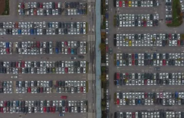
- In a big parking lot, there is trouble finding space and parking a car.
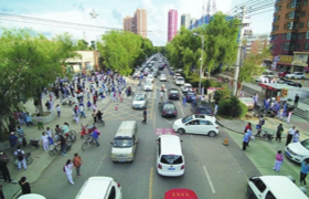
- The absence of separation of pedestrians and vehicle leads to a greater chance of traffic accidents.
(Pictures from online sources)
What these scenarios have in common is complex road conditions, slow driving speed, and necessity for drivers to have a good sense of surrounding situations.
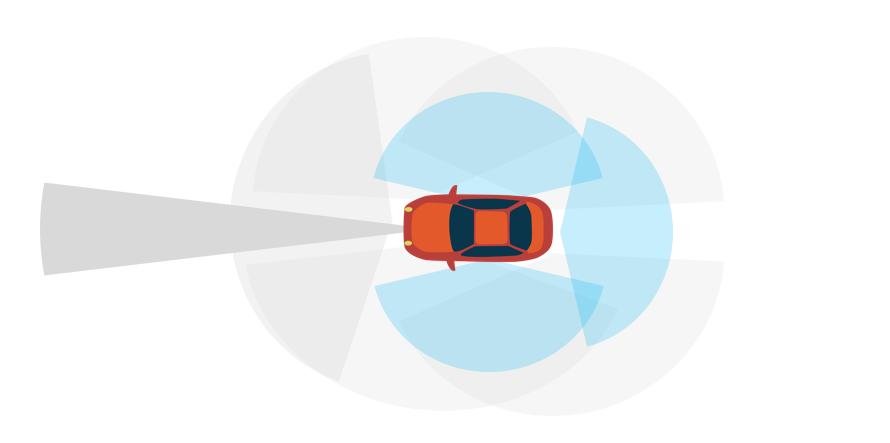
However, existing sensors are barely satisfactory in short-range coverage. Ultra sound wave radar is limited in its detection range, precision and accuracy while mmWave radar modules usually have relatively large sizes, making it hard to get mounted onto the sides of the vehicle body. In response to the market demand, the requirement of improving sensors’ detection capability and realizing full coverage within 30 meters around the vehicle needs to be addressed. On top of that, door open warning, vehicle positioning system, parking space searching and auto parking will then be able to be developed and realized.
To summarize, USRR needs to have following features in order to meet the demands of the above mentioned scenarios:
- Compact size and easy installation.
- Big FoV, enabling a vision as broad as possible.
- Capability of elevation detection.
- High performance, including in angular resolution.
- Cost-efficient.
As multiple USRR chips need to be mounted on a vehicle for full detection coverage, the price of a single USRR chip matters.
USRR aimed to meet such requirements needs a proper chip solution.
Calterah’s AiP solution
Calterah’s Antenna-in-Package chip can well meet the requirements.
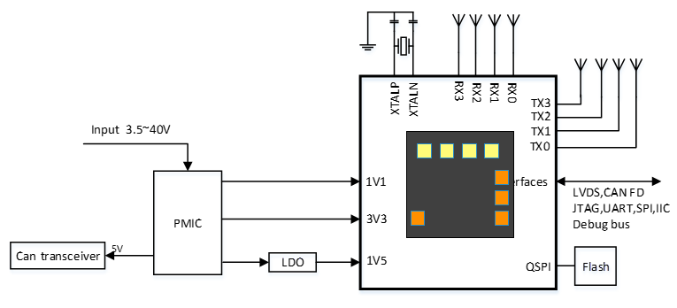
Alps AiP, a member of Alps SoC family, integrates the RF front-end, radar signal processing baseband, MPU, and HF antenna. Constructing a radar module based on Alps AiP only requires a couple extra components, including power supply chip, flash, CAN transceiver, etc.. USRR based on the AiP chip has clear advantages — high performance, easy installation due to compact size, and cost competitiveness.
Development of such a USRR module inevitably faces many challenges, such as ground clutter, antenna coupling and frequency interference. Calterah has made quite an effort in chip design, production and the underlying software in order to help downstream manufacturers overcome these challenges.
Ground clutter
USRR requires wide elevation FoV, which means richer information when detecting near-range objects but also more ground clutter.
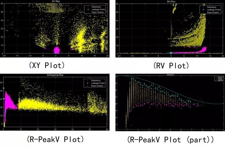
The scheme Calterah has adopted to solve the problem of ground clutter is to get a multi-frame plot and compare it with a fitting curve obtained through a large number of field tests. Any detected object whose power is above the curve will be seen as a real object. Those points below the curve will be seen as road clutter and suppressed. The range, amplitude, and even the velocity and elevation information of objects all contribute to the forming of the fitting curve. At the same time, we have come to some conclusions through actual measurements. For example, different ground pavement materials such as cement, asphalt, and dirt roads have different characteristics. By supporting adaptive fitting curve, adding more characteristic variables such as velocity and elevation, plus online training, the fitting curve can be dynamically adjusted when the vehicle enters different road conditions, which will produce better clutter suppression performance.
Antenna coupling
Antenna coupling will be worse due to physical size limitation. And non-linear distortion emerging from the coupling will cause worse angle calculation compared to the antenna-on-board scheme, and this is when antenna calibration comes into play.
Traditional calibration method targets linear distortion by linear transformation of measurements, which is not ideal for non-linear distortion. To deal with this problem, Radial Basis Function Neural Network (RBF-NN) is proposed by Calterah to handle the non-linear distortion. In RBF-NN, at the input layer is the measured angle θ of the antenna, passed through the transfer function φ in the hidden layer , and finally summed to obtain a calibrated value of the angle as the output.
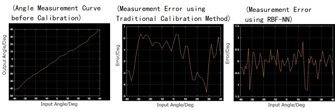
In the above images, original measurement of the angle is in the left one and has non-linear distortion. In the middle one, the error is around 5 degrees after using traditional calibration method. In the right image, the error is within 1 degree after using RBF-NN to do the calibration.
Frequency interference
Wide azimuth FoV of USRR makes itself more likely to get interference in crowded traffic scenarios, which raises the need of interference mitigation. Calterah’s AiP chip uses a holistic approach to address the need: 3 modes to avoid interference and 1 mechanism to mitigate it.
AiP chip’s FMCW generator, by randomly changing chirp parameters of one frame, avoids and mitigate possible interference.
Phase Scrambling (PS), rotating the phase of the wave.
Chirp Shifting (CS), changing the starting point of rising edge.
Frequency Hopping (FH), maintaining sweep bandwidth while changing start and stop frequencies.
When working in the same frequency band with different modulation slopes, the transmitted signal overlaps with the echo signals of other radar systems, which will cause interference. This interference may bring an additional frequency or even a larger amplitude that raises the noise floor in the time domain.
Generally, such interference can be roughly divided into: the high frequency region of the head, the low frequency region in the middle, and the high frequency region at the rear. Our interference mitigation approach is divided into two steps. The first step is to locate the interference through the absolute amplitude value of the signal and the amplitude difference between two adjacent points. The second step is to filter out interference, using two methods: 1. Zero-out, 2. Use a pre-estimated amplitude to replace the amplitude of the interference.
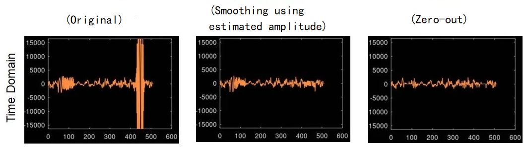
In the above images, the one on the left shows the original state of the interference in the time domain. It can be clearly observed that there are two interference sources, which cause the noise floor to rise significantly. The middle one shows the effect of using the estimated amplitude to filter out the interference. The image on the right shows the effect after zeroing out interference.
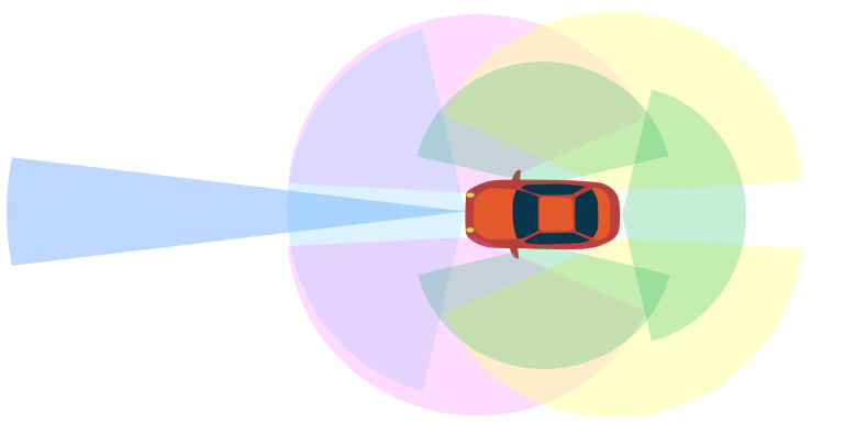
360° all-scenario chip solution
Calterah addresses the need of ultra-short-range scenes with its AiP chip and has established a 360° all-scenario chip solution —the forward-looking radar with a single Alps SoC chip or two cascaded Alps SoC chips; the front/rear corner radar with a single Alps SoC chip (2T4R or 4T4R); ultra-short-range radar enabling full short-range coverage with Alps AiP chip.
A full-stack solution based on one chip platform not only reduces the difficulty, time and cost of development, but also contributes to the standardization of sensor components. The all-scenario solution will have a rich and organized perception of the surrounding environment of the vehicle and will be more flexible for the information fusion of the upper layer.