|
Calterah’s reference design for surround view radar is developed based on its Alps AiP devices with the most compact design ever made in the industry.
Specifications
The following table lists the specifications of Calterah’s surround view radar reference design:
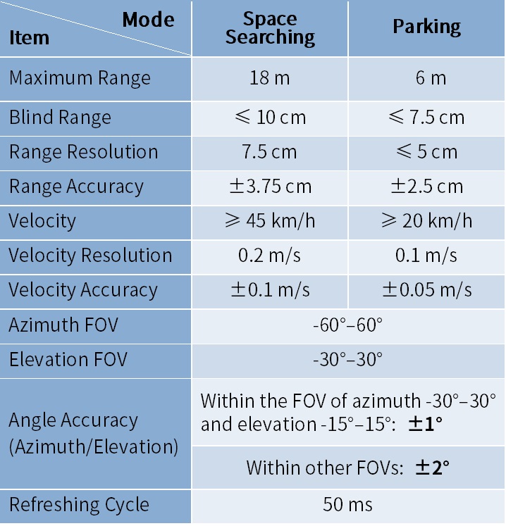
Table 1. Specifications of Surround View Radar Reference Design
Maximum Radar Range
Figure 2 and Figure 3 are the radar coverage diagrams for a corner reflector with 0-dbsm RCS.
From the diagrams, we can see the maximum radar range can reach 18 meters within the smaller FOV (azi±20° & ele±20°), and 9 meters within the larger FOV (azi±60°).
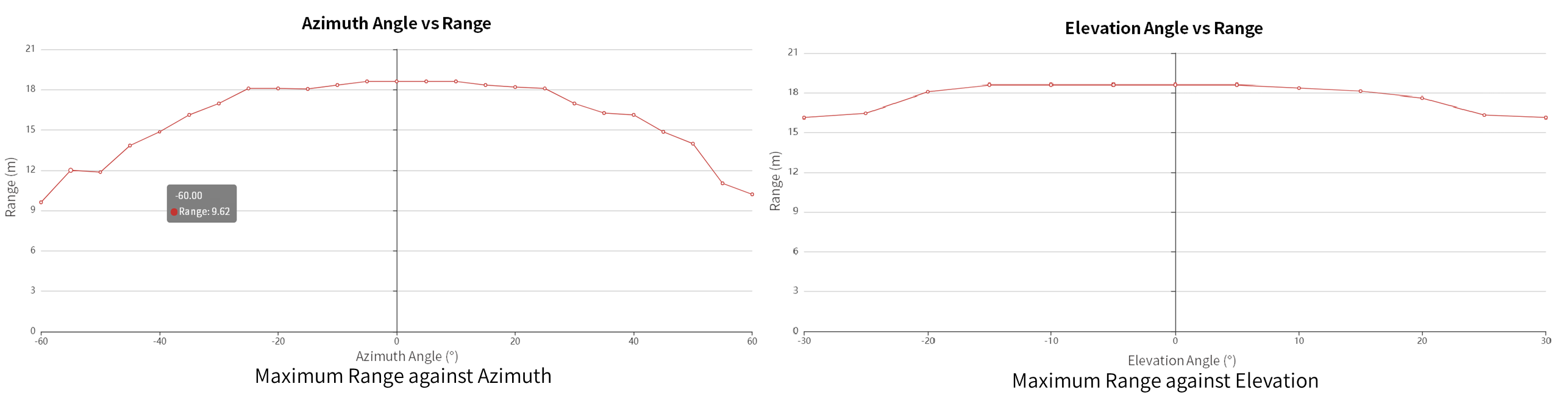 Figure 1. Maximum Radar Range against Azimuth / Elevation
Angle Measurement Accuracy of 2D DoA
Calterah’s surround view radar reference design provide the capability to measure the azimuth and elevation of objects simultaneously. By adopting the neural network algorithm to correct distortion in angle measurement and the coupling between azimuth and elevation, Calterah has significantly improved the accuracy of measurement.
Figure 3 and Figure 4 show the measurement accuracy after calibration. The horizontal axis refers to the actual elevation of the target and the vertical axis the actual azimuth. The yellow spots represent large errors while blue and green areas represent smaller ones.
From the figures, we can see errors in both azimuth and elevation measurement are below 1° within the FOV of azimuth being 30° and elevation being 15°, and below 2° in other angle range.
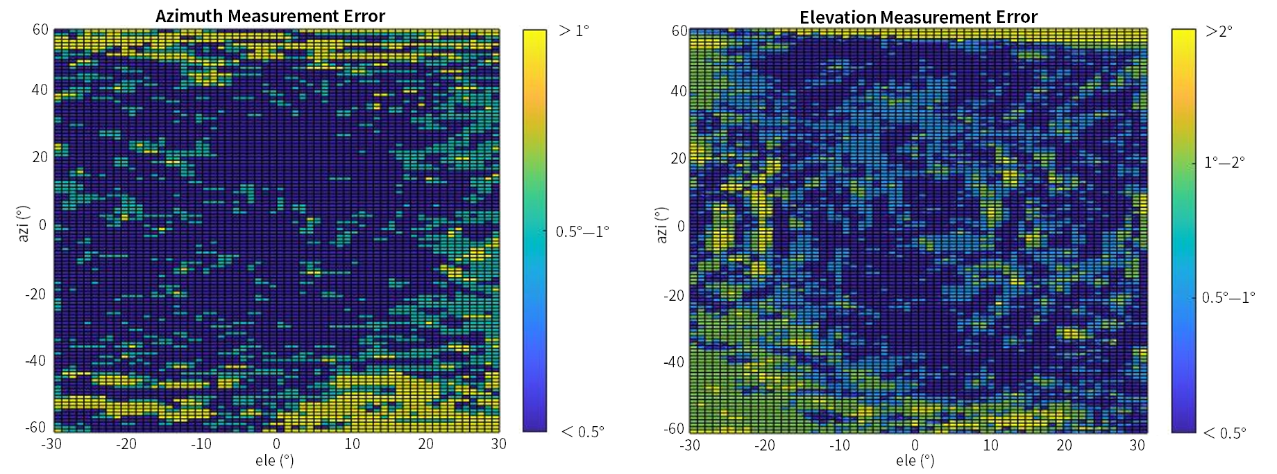 Figure 2. Error of Azimuth and Elevation Measurement
Point Cloud Data of Road Testing
Figure 5 and Figure 6 show a road test scenario of Calterah’s surround view radar reference design and the resulting point cloud data of one frame (the XY view and the YZ view).
In the one frame of point cloud data, the curb, ground clutter, tires, trees, vehicles and traffic barrier poles are detected with their accurate positions and heights provided. All these make possible the subsequent radar SLAM (Simultaneous Localization And Mapping).

Figure 3. Road Test Scenario (with Curb)
 Figure 4. Single-Frame Test Results (XY View)
 Figure 5. Single-Frame Test Results (YZ View)
Demo of Surround View Radar SLAM
The 3D SLAM result of the surround view radar is shown in the video. After multiple frames of point cloud data are accumulated and mapped, a 3D contour of the vehicle is formed and empty parking spaces are identified.